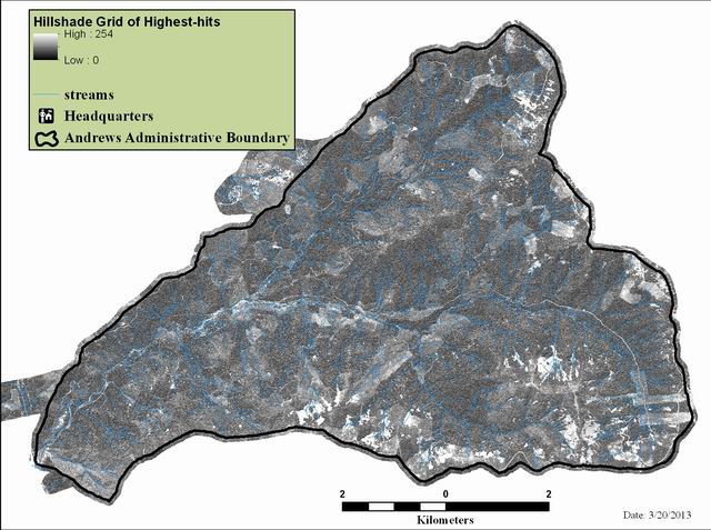
Hillshade grid generated from 2008 LiDAR 1 meter highest-hits DEM

arcgis export format
Thumbnail

Tags
topography, DEM, catography, LiDAR


Summary

The purpose of the hillshade is to provide topographic relief for maps, figures, and visualizations. The hillshade can also be used to capture features (roads, buildings, bridges, vegetation), and to locate geological features such as landslides, stream channel characteristics, and earth movement. This data set is suitable for detailed work. Visualizations of the raw point clouds would be appropriate for those looking for sub-meter accuracy.

Description

The hillshade was generated from the 1 meter highest-hits digital elevation model (DEM) based on the 2008 LiDAR flight over the Andrews Experimental Forest. The hillshade is at 1 meter resolution, and provides a detailed visualization of the forest, including the vegetation. The hillshade command in spatial analyst was used with a sun azmuth of 345 degress and the altitude was set for 65 degrees.

Credits

Use limitations

Extent

West -122.277460   East -122.099580
North 44.282961   South 44.196797

Scale Range
Maximum (zoomed in) 1:5,000
Minimum (zoomed out) 1:50,000

ArcGIS Metadata 

Topics and Keywords 

Themes or categories of the resource  elevation, geoscientificInformation, imageryBaseMapsEarthCover


*Content type  Downloadable Data


Place keywords  Oregon, Willamette Basin, Blue River Watershed, HJ Andrews Experimental Forest

Theme keywords  topography, DEM, elevation, mapping, LiDAR

Thesaurus
Title  Andrews Forest LTER Thesaurus


Citation 

Title Hillshade grid generated from 2008 LiDAR 1 meter highest-hits DEM
Creation date 2008-11-18 00:00:00
Publication date 2013-01-04 00:00:00


Presentation formats  digital image
FGDC geospatial presentation format  raster digital data


Other citation details gi01011 hja_hh_shd


Citation Contacts 

Responsible party
Individual's name Theresa Valentine
Organization's name Corvallis Forest Science Laboratory
Contact's position Spatial Information Manager
Contact's role  point of contact


Contact information
Phone
Voice 541-750-7333
Fax 541-758-7760

Address
Type both
Delivery point 3200 SW Jefferson Way
City Corvallis
Administrative area Oregon
Postal code 97332
Country US
e-mail addresstvalentine@fs.fed.us or theresa.valentine@orst.edu

Hours of service m-f 8:00am-4:00pm


Responsible party
Individual's name Theresa Valentine
Organization's name Corvallis Forest Science Laboratory
Contact's position Spatial Information Manager
Contact's role  processor


Contact information
Phone
Voice 541-750-7333
Fax 541-758-7760

Address
Type both
Delivery point 3200 SW Jefferson Way
City Corvallis
Administrative area Oregon
Postal code 97332
Country US
e-mail addresstvalentine@fs.fed.us or theresa.valentine@orst.edu

Hours of service m-f 8:00am-4:00pm


Responsible party
Organization's name Watershed Sciences
Individual's name Russell Faux
Contact's position Principle and Co-CEO
Contact's role  originator


Contact information
Phone
Voice 541-752-1204
Fax 541-752-3770

Address
Type both
Delivery point 517 SW 2nd St. Suite 400
City Corvallis
Administrative area OR
Postal code 97333
Country US


Resource Details 

Dataset languages* English (UNITED STATES)
Dataset character set  utf8 - 8 bit UCS Transfer Format


Status  completed
Spatial representation type* grid


Spatial resolution
Dataset's scale
Scale denominator 1

*Processing environment Microsoft Windows 7 Version 6.1 (Build 7601) Service Pack 1; Esri ArcGIS 10.1.1.3143


ArcGIS item properties
*Name hja_hh_shd
*Location file://J:\hja83\lidar\hja_hh_shd
*Access protocol Local Area Network

Extents 

Extent
Description
The LiDAR lazer data was collect by airplane on August 10 and 11, 2008.
Temporal extent
Beginning date 2008-08-10 00:00:00
Ending date 2008-08-11 00:00:00

Extent
Geographic extent
Bounding rectangle
Extent type  Extent used for searching
*West longitude -122.277460
*East longitude -122.099580
*North latitude 44.282961
*South latitude 44.196797
*Extent contains the resource Yes

Extent in the item's coordinate system
*West longitude 557736.000000
*East longitude 571848.000000
*South latitude 4894124.000000
*North latitude 4903556.000000
*Extent contains the resource Yes

Resource Points of Contact 

Point of contact
Individual's name Theresa Valentine
Organization's name Corvallis Forest Science Laboratory
Contact's position Spatial Information Manager
Contact's role  point of contact


Contact information
Phone
Voice 541-750-7333
Fax 541-758-7760

Address
Type both
Delivery point 3200 SW Jefferson Way
City Corvallis
Administrative area Oregon
Postal code 97332
Country US
e-mail addresstvalentine@fs.fed.us or theresa.valentine@orst.edu

Hours of service m-f 8:00am-4:00pm


Resource Maintenance 

Resource maintenance
Update frequency  not planned


Maintenance contact
Individual's name Theresa Valentine
Organization's name Corvallis Forest Science Laboratory
Contact's position Spatial Information Manager
Contact's role  distributor


Contact information
Phone
Voice 541-750-7333
Fax 541-758-7760

Address
Type both
Delivery point 3200 SW Jefferson Way
City Corvallis
Administrative area Oregon
Postal code 97332
Country US
e-mail addresstvalentine@fs.fed.us or theresa.valentine@orst.edu

Hours of service m-f 8:00am-4:00pm


Spatial Reference 

ArcGIS coordinate system
*Type Projected
*Geographic coordinate reference GCS_North_American_1983
*Projection NAD_1983_UTM_Zone_10N
*Coordinate reference details
Projected coordinate system
Well-known identifier 26910
X origin -5120900
Y origin -9998100
XY scale 450445547.3910538
Z origin -100000
Z scale 10000
M origin -100000
M scale 10000
XY tolerance 0.001
Z tolerance 0.001
M tolerance 0.001
High precision true
Latest well-known identifier 26910
Well-known text PROJCS["NAD_1983_UTM_Zone_10N",GEOGCS["GCS_North_American_1983",DATUM["D_North_American_1983",SPHEROID["GRS_1980",6378137.0,298.257222101]],PRIMEM["Greenwich",0.0],UNIT["Degree",0.0174532925199433]],PROJECTION["Transverse_Mercator"],PARAMETER["False_Easting",500000.0],PARAMETER["False_Northing",0.0],PARAMETER["Central_Meridian",-123.0],PARAMETER["Scale_Factor",0.9996],PARAMETER["Latitude_Of_Origin",0.0],UNIT["Meter",1.0],AUTHORITY["EPSG",26910]]

Reference system identifier
*Value 26910
*Codespace EPSG
*Version 7.11.2


Spatial Data Properties 

Georectified Grid
*Number of dimensions 2


Axis dimensions properties
Dimension type  column (x-axis)
*Dimension size 14112
*Resolution  1.000000 Meter

Axis dimensions properties
Dimension type  row (y-axis)
*Dimension size 9432
*Resolution  1.000000 Meter

*Cell geometry  area
*Point in pixel  center


*Transformation parameters are available Yes


*Check points are available No


Corner points
*Point 557736.000000 4894124.000000
*Point 557736.000000 4903556.000000
*Point 571848.000000 4903556.000000
*Point 571848.000000 4894124.000000

*Center point 564792.000000 4898840.000000


ArcGIS Raster Properties
General Information
*Pixel depth 8
*Compression type RLE
*Number of bands 1
*Raster format GRID
*Source type continuous
*Pixel type unsigned integer
*No data value 255
*Has colormap No
*Has pyramids Yes


Spatial Data Content 

Image Description
*Type of information  physical measurement
Attribute described by cell values value for shading based on solar azimuth and angle.


Band information
*Description hja_hh_shd
*Maximum value 254.000000
*Minimum value 0.000000
Units
Symbol [k]

*Number of bits per value 8


Illumination elevation angle 65
Illumination azimuth angle 345


Image quality code
Value none


Processing level code
Value none


Triangulation has been performed No
Radiometric calibration is available No
Camera calibration is available No
Film distortion information is available No
Lens distortion information is available No


Data Quality 

Scope of quality information


Data quality report - Absolute external positional accuracy
Dimension vertical


Test date 2009-11-14 01:00:00


Measure name Manual System Calibration
Measure description The vertical accuracy of the LiDAR data is described as the mean and standard deviation (sigma ~ σ) of divergence of LiDAR point coordinates from RTK ground survey point coordinates. To provide a sense of the model predictive power of the dataset, the root mean square error (RMSE) for vertical accuracy is also provided. These statistics assume the error distributions for x, y, and z are normally distributed, thus we also consider the skew and kurtosis of distributions when evaluating error statistics. Statements of statistical accuracy apply to fixed terrestrial surfaces only and may not be applied to areas of dense vegetation or steep terrain. Additional control points are needed to assess accuracy in different land covers


Standard procedure identifier
Value none


Quantitative test results
Value 1
Units
Symbol m

Evaluation type  direct internal
Evaluation method see above
Evaluation procedure
Title LIDAR REMOTE SENSING DATA COLLECTION: HJ Andrews and Willamette NF
Publication date 2008-11-14 00:00:00


Edition 1
Edition date 2008-11-14


Resource location online
Locationhttp://andrewsforest.oregonstate.edu/lter/data/aerial/hj_andrews_report.pdf
Function performed  download


Conformance test results
Test passed Yes
Result explanation Project Average = 0.12 m o Median Relative Accuracy = 0.12 m o 1σ Relative Accuracy = 0.13 m o 2σ Relative Accuracy = 0.19 m


Product specification
Title Accuracy
Creation date 2008-11-15 00:00:00


Presentation formats  digital document
FGDC geospatial presentation format  document


Resource location online
Locationhttp://andrewsforest.oregonstate.edu/lter/data/aerial/hj_andrews_report.pdf
Access protocol pdf file
Name LiDAR Remote Sensing Data Collection: HJ Andrews and Willamette NF, November 14, 2008
Description  chapeter on accuracy assessment
Function performed  download
Application profile pdf file


Data quality report - Absolute external positional accuracy
Dimension horizontal


Test date 2008-11-14 00:00:00


Measure description LiDAR survey datasets were referenced to the 1 Hz static ground GPS data collected over presurveyed monuments with known coordinates. While surveying, the aircraft collected 2 Hz kinematic GPS data, and the onboard inertial measurement unit (IMU) collected 200 Hz aircraft attitude data. Realm Survey Suite was used to process the kinematic corrections for the aircraft. The static and kinematic GPS data were then post-processed after the survey to obtain an accurate GPS solution and aircraft positions. POSPAC was used to develop a trajectory file that includes corrected aircraft position and attitude information. The trajectory data for the entire flight survey session were incorporated into a final smoothed best estimated trajectory (SBET) file that contains accurate and continuous aircraft positions and attitudes.


Standard procedure identifier
Value LiDAR Remote Sensign Data Collection: HJ Andrews and Willamette NF November 14,2008


Reference that defines the value
Title LiDAR Remote Sensign Data Collection: HJ Andrews and Willamette NF November 14,2008
Creation date 2008-11-14 00:00:00
Publication date 2008-11-14 00:00:00


Presentation formats  digital document
FGDC geospatial presentation format  document


Resource location online
Locationhttp://andrewsforest.oregonstate.edu/lter/data/aerial/hj_andrews_report.pdf
Access protocol pdf file
Function performed  download


Quantitative test results
Value 1
Units
Symbol m

Evaluation type  direct internal
Evaluation method Manual System Calibration: Calibration procedures for each mission require solving geometric relationships that relate measured swath-to-swath deviations to misalignments of system attitude parameters. Corrected scale, pitch, roll and heading offsets were calculated and applied to resolve misalignments. The raw divergence between lines was computed after the manual calibration was completed and reported for each study area. 2. Automated Attitude Calibration: All data were tested and calibrated using TerraMatch automated sampling routines. Ground points were classified for each individual flight line and used for line-to-line testing. System misalignment offsets (pitch, roll and heading) and scale were solved for each individual mission and applied to respective mission datasets. The data from each mission were then blended when imported together to form the entire area of interest. 3. Automated Z Calibration: Ground points per line were utilized to calculate the vertical divergence between lines caused by vertical GPS drift. Automated Z calibration was the final step employed for relative accuracy calibration.
Evaluation procedure
Title LiDAR Remote Sensign Data Collection: HJ Andrews and Willamette NF November 14,2008
Creation date 2008-11-14 00:00:00
Publication date 2008-11-14 00:00:00


Edition 1
Edition date 2008-11-14


Presentation formats  digital document
FGDC geospatial presentation format  document


Resource location online
Locationhttp://andrewsforest.oregonstate.edu/lter/data/aerial/hj_andrews_report.pdf
Access protocol pdf
Function performed  download


Data quality report - Completeness omission
Test date 2008-11-12 00:00:00


Measure description see description in on-line documentation


Standard procedure identifier
Value none


Evaluation type  direct internal
Evaluation method see description in on-line documentation
Evaluation procedure
Title LiDAR Remote Sensing Data Collection: HJ Andrews and Willamette NF
Creation date 2008-11-14 00:00:00
Publication date 2008-11-14 00:00:00


Edition 1
Edition date 2008-11-14


Resource location online
Locationhttp://andrewsforest.oregonstate.edu/lter/data/aerial/hj_andrews_report.pdf
Access protocol pdf
Function performed  download


Data quality report - Conceptual consistency
Measure description see report from Watershed Sciences


Standard procedure identifier
Value Document


Evaluation type  direct external
Evaluation method see documentation from Watershed Sciences
Evaluation procedure
Title LiDAR Remote Senseing Data Collection: HJ Andrews and Willamette National Forests
Creation date 2008-11-14 00:00:00


Responsible party
Organization's name Watershed Sciences
Contact's role  originator


Resource location online
Locationhttp://andrewsforest.oregonstate.edu/lter/data/aerial/hj_andrews_report.pdf
Function performed  download


Lineage 

Lineage statement
The 1 meter highest-hits DEM was used to produce this dataset (hja__hh). The
                hillshade command in spatial analyst was used with a sun azmuth of 345 degress and
                the altitude was set for 65 degrees. 
Process step
When the process occurred 2008-09-01 00:00:00
Description Simultaneous with the airborne data collection mission, we conducted multiple static (1 Hz recording frequency) ground surveys over monuments with known coordinates (Table 1). Indexed by time, these GPS data are used to correct the continuous onboard measurements of aircraft position recorded throughout the mission. Multiple sessions were processed over the same monument to confirm antenna height measurements and reported position accuracy. After the airborne survey, these static GPS data were then processed using triangulation with Continuously Operating Reference Stations (CORS) stations, and checked against the Online Positioning User Service (OPUS2) to quantify daily variance. Controls were located within 13 nautical miles of the mission area(s).


Process step
When the process occurred 2008-10-01 00:00:00
Description Laser point coordinates were computed using the REALM software based on independent data from the LiDAR system (pulse time, scan angle), and aircraft trajectory data (SBET). Laser point returns (first through fourth) were assigned an associated (x, y, z) coordinate along with unique intensity values (0-255). The data were output into large LAS v. 1.1 files; each point maintains the corresponding scan angle, return number (echo), intensity, and x, y, z (easting, northing, and elevation) information. These initial laser point files were too large for subsequent processing. To facilitate laser point processing, bins (polygons) were created to divide the dataset into manageable sizes (< 500 MB). Flightlines and LiDAR data were then reviewed to ensure complete coverage of the study area and positional accuracy of the laser points. Laser point data were imported into processing bins in TerraScan, and manual calibration was performed to assess the system offsets for pitch, roll, heading and scale (mirror flex). Using a geometric relationship developed by Watershed Sciences, each of these offsets was resolved and corrected if necessary. LiDAR points were then filtered for noise, pits (artificial low points) and birds (true birds as well as erroneously high points) by screening for absolute elevation limits, isolated points and height above ground. Each bin was then manually inspected for remaining pits and birds and spurious points were removed. In a bin containing approximately 7.5-9.0 million points, an average of 50-100 points are typically found to be artificially low or high. Common sources of non-terrestrial returns are clouds, birds, vapor, haze, decks, brush piles, etc. Internal calibration was refined using TerraMatch. Points from overlapping lines were tested for internal consistency and final adjustments were made for system misalignments (i.e., pitch, roll, heading offsets and scale). Automated sensor attitude and scale corrections yielded 3-5 cm improvements in the relative accuracy. Once system misalignments were corrected, vertical GPS drift was then resolved and removed per flight line, yielding a slight improvement (<1 cm) in relative accuracy. The TerraScan software suite is designed specifically for classifying near-ground points (Soininen, 2004). The processing sequence began by ‘removing’ all points that were not ‘near’ the earth based on geometric constraints used to evaluate multi-return points. The resulting bare earth (ground) model was visually inspected and additional ground point modeling was performed in site-specific areas to improve ground detail. This manual editing of grounds often occurs in areas with known ground modeling deficiencies, such as: bedrock outcrops, cliffs, deeply incised stream banks, and dense vegetation. In some cases, automated ground point classification erroneously included known vegetation (i.e., understory, low/dense shrubs, etc.). These points were manually reclassified as non-grounds. Ground surface rasters were developed from triangulated irregular networks (TINs) of ground points.


Process step
When the process occurred 2008-10-16 00:00:00
Description Resolve kinematic corrections for aircraft position data using kinematic aircraft GPS and static ground GPS data. Software: Waypoint GPS v.7.60 2. Develop a smoothed best estimate of trajectory (SBET) file that blends post-processed aircraft position with attitude data (sensor heading, position, and attitude are calculated throughout the survey). Software: IPAS v.1.4 3. Calculate laser point position by associating SBET position to each laser point return time, scan angle, intensity, etc. Create raw laser point cloud data for the entire survey in *.las (ASPRS v1.1) format. Software: ALS Post Processing Software 4. Import raw laser points into subset bins (less than 500 MB, to accommodate file size constraints in processing software). Perform manual relative accuracy calibration and filter for pits/birds. Classify ground points for individual flight lines (to be used for relative accuracy testing and calibration). Software: TerraScan v.7.012 5. Test relative accuracy using ground classified points per each flight line. Perform automated line-to-line calibrations for system attitude parameters (pitch, roll, heading), mirror flex (scale) and GPS/IMU drift. Perform calibrations on ground classified points from paired flight lines. Every flight line is used for relative accuracy calibration. Software: TerraMatch v.7.004 6. Import position and attitude data. Classify ground and non-ground points. Assess statistical absolute accuracy via direct comparisons of ground classified points to ground RTK survey data. Convert data to orthometric elevations (NAVD88) by applying a Geoid03 correction.


Process step
When the process occurred 2008-10-16 00:00:00
Description The LiDAR survey uses a Leica ALS50 Phase II laser system. For the HJ Andrews and Willamette NF study areas, the sensor scan angle was ±14o from nadir1 with a pulse rate designed to yield an average native density (number of pulses emitted by the laser system) of 8 points per square meter over terrestrial surfaces. All study areas were surveyed with an opposing flight line side-lap of =50% (=100% overlap) to reduce laser shadowing and increase surface laser painting. The Leica ALS50 Phase II system allows up to four range measurements (returns) per pulse, and all discernable laser returns were processed for the output dataset. It is not uncommon for some types of surfaces (e.g. dense vegetation or water) to return fewer pulses than the laser originally emitted. These discrepancies between ‘native’ and ‘delivered’ density will vary depending on terrain, land cover and the prevalence of water bodies. To accurately solve for laser point position (geographic coordinates x, y, z), the positional coordinates of the airborne sensor and the attitude of the aircraft were recorded continuously throughout the LiDAR data collection mission. Aircraft position was measured twice per second (2 Hz) by an onboard differential GPS unit. Aircraft attitude was measured 200 times per second (200 Hz) as pitch, roll and yaw (heading) from an onboard inertial measurement unit (IMU). To allow for post-processing correction and calibration, aircraft/sensor position and attitude data are indexed by GPS time


Process step
When the process occurred 2008-11-11 00:00:00
Description The hillshade command in spatial analyst was used with a sun azmuth of 345 degress and the altitude was set for 65 degrees.


Process contact
Individual's name Theresa Valentine
Organization's name Corvallis Forest Science Laboratory
Contact's position Spatial Information Manager
Contact's role  processor


Contact information
Phone
Voice 541-750-7333
Fax 541-758-7760

Address
Type both
Delivery point 3200 SW Jefferson Way
City Corvallis
Administrative area Oregon
Postal code 97332
Country US
e-mail addresstvalentine@fs.fed.us or theresa.valentine@orst.edu

Hours of service m-f 8:00am-4:00pm


Geoprocessing history 

Process
Process name
Date 2008-11-18 17:26:22
Tool location C:\Program Files\ArcGIS\ArcToolbox\Toolboxes\Spatial Analyst Tools.tbx\HillShade
Command issued
HillShade E:\Rasters\Highest_Hit\hja_hh J:\hja83\lidar\hja_hh_shd 345 65 NO_SHADOWS 1
Include in lineage when exporting metadata No


Distribution 

Distribution format
Version 10.0
Name arcgis export format


Distribution format
*Name Raster Dataset
Version 7-zip


Transfer options
Online source
Locationhttp://andrewsforest.oregonstate.edu/data/studies/spatialdata/gi01011.zip
Function performed  download

Fields 

Details for object hja_hh_shd.vat 
*Type Table
*Row count 255
Definition
unknown
Definition source
unknown


Field Rowid
 
*Alias Rowid
*Data type OID
*Width 4
*Precision 0
*Scale 0
*Field description
Internal feature number.
*Description source
ESRI
*Description of values Sequential unique whole numbers that are automatically generated.


Measurement frequency  not planned


Field VALUE
 
*Alias VALUE
*Data type Integer
*Width 4
*Precision 0
*Scale 0
Field description
value for shading based on solar azimuth and angle.
The value represents illumination, where 0 = shadow, and 255 = full sunlight.
Description source
esri
Range of values
Minimum value 0
Maximum value 255
Units of measure dimensionless


Field COUNT
 
*Alias COUNT
*Data type Integer
*Width 4
*Precision 0
*Scale 0
Field description
number of times a value code occures in the grid
Description source
esri
Description of values sum of cells for particular values


Measurement frequency  not planned


Metadata Details 

Metadata language English (UNITED STATES)
Metadata character set  utf8 - 8 bit UCS Transfer Format


Scope of the data described by the metadata  dataset
Scope name* dataset


*Last update 2013-06-13


ArcGIS metadata properties
Metadata format ArcGIS 1.0
Standard or profile used to edit metadata FGDC


Created in ArcGIS for the item 2008-11-18 17:26:21
Last modified in ArcGIS for the item 2013-06-13 16:40:52


Automatic updates
Have been performed Yes
Last update 2013-06-13 16:40:52


Metadata Contacts 

Metadata contact
Individual's name Theresa Valentine
Organization's name Corvallis Forest Science Laboratory
Contact's position Spatial Information Manager
Contact's role  custodian


Contact information
Phone
Voice 541-750-7333
Fax 541-758-7760

Address
Type both
Delivery point 3200 SW Jefferson Way
City Corvallis
Administrative area Oregon
Postal code 97332
Country US
e-mail addresstvalentine@fs.fed.us or theresa.valentine@orst.edu

Hours of service m-f 8:00am-4:00pm


Thumbnail and Enclosures 

Thumbnail
Thumbnail type  JPG

FGDC Metadata (read-only) 

Entities and Attributes